
|
Microscope - Detector Settings > Dr. Probe / Documentation / GUI / Microscope |
|
STEM detectors are defined by rings or ring segments placed the diffraction plane below the sample. Images of multiple detectors can be simultaneously calculated. The detector setup allows you also to specify radial sensitivity profiles to achieve even better quantitative comparisons between experiment and simulation.
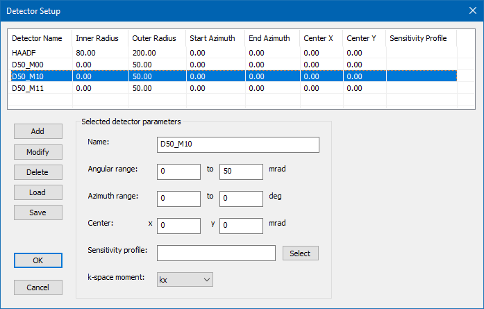
Defined detectors are shown in the list with their parameters. When selecting a detector in the list, the parameters are copied to the edit controls in the lower are of the dialog.
Each detector has a unique detector name which will be used as file suffix when saving simulated STEM images to files. It is therefore recommended to use only short names such as "BF", "ABF", and "HAADF".
Ring or ring segment detectors are specified by an angular range in diffraction plane, limited by an inner radius and by an outer radius in mrad units.
Ring segments require also a limited azimuth range specified in degrees measured with respect to the x axis of the simulation box. In order to prevent ambiguities, please define the azimuthal range using angles beta1 (left edit box) and beta2 (right edit box) between 0 deg and 360 deg with beta1 < beta2. Negative angles may also be used for example to define a segment across the x axis with beta1 = -45 deg and beta2 = 45 deg.
Detectors may be shifted away from the optics axis in the diffraction plane. The shift of the detector center is specified here by two parameters denoting the center coordinates (horizontal and vertical) in the diffraction plane using mrad units.
By default, the detector sensitivity is assumed to be 1, which means that the absolute square of the electron wave function is registered with 100% strength by the detector. The sensitivity of each detector can be changed by linking a file that describes a relative radial sensitivity profile. Select a file from disk by pressing the button next to the edit box or type the file name.
The k-space moment provides a tool to calculate the first moments of the intensity distribution in the diffraction plane, labelled kx and ky. For default bucket STEM detectors this option should be set to None, which corresponds to the 0th moment of the distribution. Dividing 1st moment and 0th moment images corresponds to the calculation of the center of mass.
The detector data and the detector list content can be manipulated by the column of buttons on the lower left side of the dialog.
By pressing the [Add] button, a new detector is added to the end of the current list including the parameters set on the right side. It is required that the new detector has a unique name, which differs from the detector names already contained in the list.
An existing detector definition can be changed by using the [Modify] button. With this function the parameters of the detector which is currently selected in the list are set equal to the parameters in the edit boxes on the right side of the dialog.
The currently selected detector is deleted from the list when pressing the [Delete] button.
The buttons [Load from file] and [Save to file] allow you to load and store lists of detector definitions to files. Detector parameter files are text files containing a specific sequence of parameters and can also be used directly with the command-line tool MSA for STEM image simulations. When loading a list of detectors from a file, the existing detector definitions are deleted.
The list of detector definitions can be saved to file by pressing the [Save to file] button.
Last update: June 25, 2021 contact disclaimer(de)