|
|
Program MSA |

|
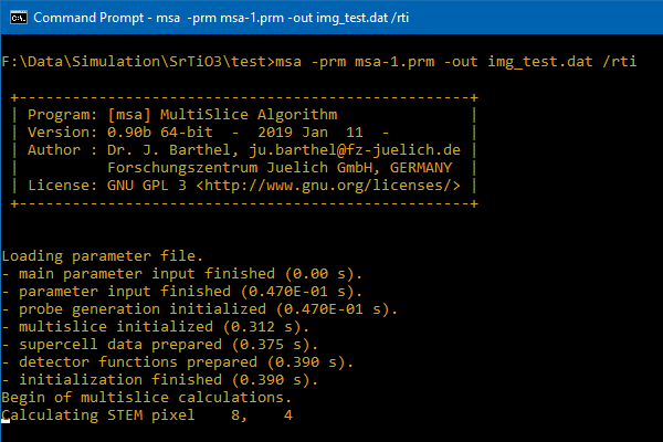
The program MSA calculates the diffraction of fast electrons in an atomic structure with the multislice algorithm. The results can be complex-valued wave functions, STEM images, CBED patterns, or probe intensity distributions.

The program is compiled for single-thread calculations and can be called from command-line shell or from other programs on 64-bit operating systems (Microsoft Windows, Linux and Max OSX). It is controlled via a parameter list provided in a text file and by calling options.
Examples
STEM image simulation controlled via parameter file:
msa -prm msa.prm -out STEMimage.dat
STEM image convolution with a specific geometric source size:
msa -prm msa.prm -in STEMimage.dat -out STEMimage_convoluted.dat -sr 0.06
4D-STEM simulation controlled via parameter file storing a thickness series of CBED patterns
for each scan pixel:
msa -prm msa.prm -out 4D-STEM.dat /3dout /pdif
TEM exit-plane wave function:
msa -prm msa-tem.prm -out wavefunc.dat /ctem
TEM exit-plane wave function with object tilt:
msa -prm msa-tem.prm -out wavefunc_tilted.dat -otx 5.4 -oty 1.5 /ctem
Multislice
The multislice algorithm is used for calculating the electron diffraction by the electrostatic potential of an atomic structure [J.M. Cowley and A.F. Moodie, Acta Cryst. 10 (1957) p. 609-618]. In this approach the scattering by a thicker sample is described as a sequence of scattering events on thin sample slices taken along the main direction of the incident electrons. Between the scattering events, the electron wave function is propagated in free space towards the next slice.
The approach of sequential scattering and propagation can be implemented in an efficient numerical form. The the scattering of electrons from projected slice potentials is a multiplication of the electron wave function with an object transmission function (phase grating). The subsequent free-space propagation to the next slice plane is calculated by a multiplication of the scattering result with a propagator function in Fourier-space. The calculation for a thick sample comprises thus two multiplications, one forward and one inverse Fourier transform for each structure slice.
MSA supports frozen-phonon calculations as well as calculations with absorptive potentials. Frozen-phonon configurations of the scattering potentials are expected to be pre-calculated e.g. by the program CELSLC or the Dr. Probe GUI and are stored in input slice files. During the calculation MSA selects and applies a random frozen-phonon variant of each slice. By this way, each single multislice calculation, e.g. for each STEM image pixel, is effectively calculated with an individual frozen-phonon configuration of the whole sample (detailed description).
STEM or coherent TEM
Calculations for STEM and TEM differ by the form of the incident wave function and by the way how the electron wave function obtained at the exit-plane of the sample is transferred into image intensities.
For STEM image calculations, the incident electron wave function is converging into a focused probe and scanned over the sample. For each probe position, the wave function below the sample is analyzed in diffraction space, where the absolute square is integrated for given detector areas, generating STEM images. This means that MSA can be used in its default STEM mode to calculate STEM images, CBED and even scanned CBED (aka. 4D-STEM) data sets.
For TEM image calculations (option /ctem), the incident electron wave is approximated by
a plane wave and the electron wave below the sample is passed further through imaging
optics towards a detector where the absolute square is taken in real space. In the TEM case,
MSA can be used to calculate the electron wave function below the sample (exit-plane wave
function). The calculation of TEM image intensities including the application of wave
aberrations, partial coherence and incoherent contrast dampening effects are done by the
program WAVIMG, which is also available with the
Dr. Probe software package.
Last update: Jan 27, 2019 contact disclaimer(de)